


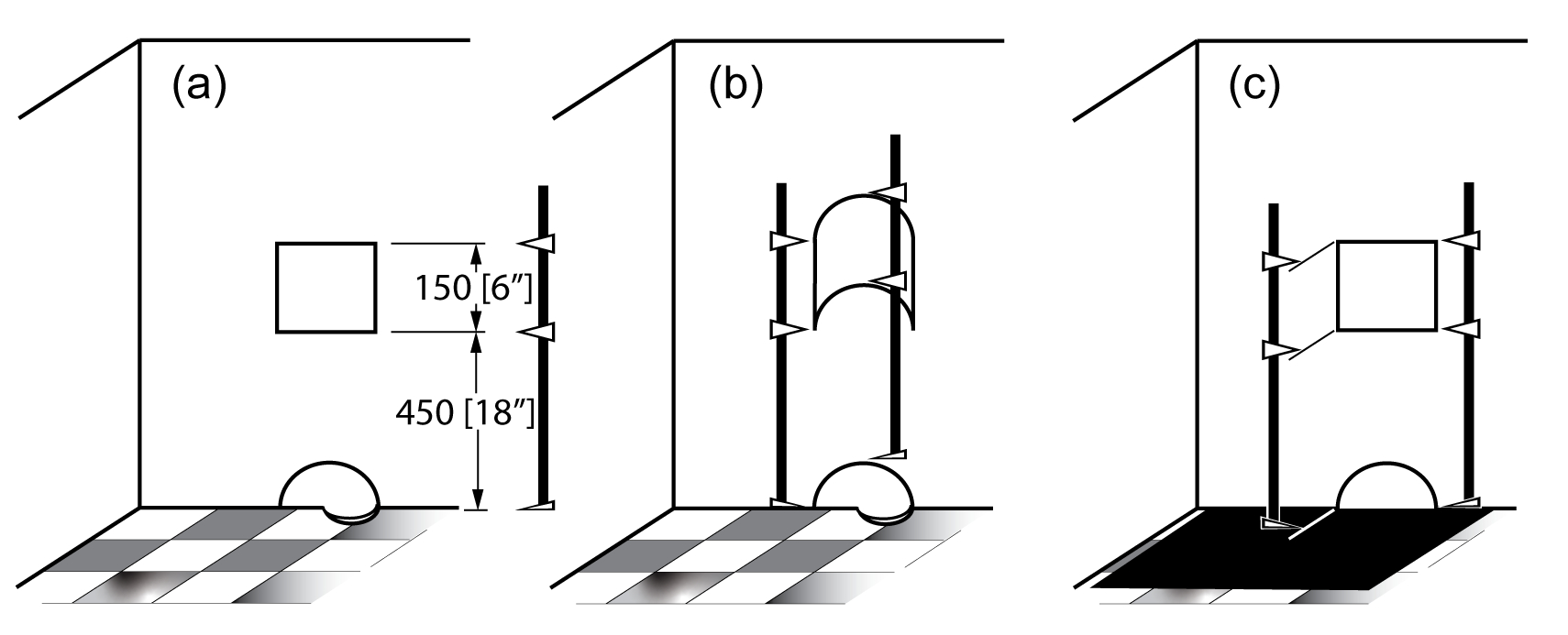
Figure 1. Conventional location dimensions. Photos Credit, all images: Profile Services and OASIC Consulting
As a decision-maker in the manufacturing sector, you are familiar with (if not a devotee of) Lean, Six Sigma, Operational Excellence and similar continuous improvement approaches. One of the essential takeaways from continuous improvement technologies is that you need meaningful data to make decisions. For example, suppose you are like most mold manufacturers and rely on conventional tolerancing. In that case, you may eventually feel frustrated as you try to figure out why some of your parts pass inspection but fail in use. Tolerance stack-ups based on conventional tolerances are meaningless and can’t be trusted. Inspection based on conventional tolerances only addresses the size and poorly addresses location, not orientation or form.
Before considering an alternative dimensioning system like geometric dimensioning and tolerance (GD&T), it is important to understand what conventional tolerancing lacks. So, let’s look at the typical state of mold manufacturing concerning tolerancing.


A mold designer communicates design intent by dimensioning and tolerancing the drawings and 3D models they create. Four attributes define the features of a workpiece: location, orientation, size and form. Conventional tolerancing applies to the location and size of features but does not define the form (flatness, straightness, circularity and cylindricity) of these features. In addition, orientation is rarely controlled beyond parallelism or perpendicularity between surfaces. As a result, conventional tolerances for angled features produce significant issues. Specified as plus-minus degrees (± degrees), conventional angular tolerances result in wedge-shaped tolerance zones, allowing the least deviation from nominal for geometry closest to the inflection point of the tolerance zone and the greatest allowable deviation at the other end of the toleranced feature. Because of the deficiencies of conventional tolerancing, shops tend to work to their tightest process capabilities rather than the tolerances needed for part functionality, which unnecessarily drives up costs.
Conventional Tolerancing
Dimensions provide the nominal (or target) values for a feature’s geometries and location. Tolerances provide the allowable deviation that a feature’s actual geometries and location may have from the nominal value while providing the expected functionality.
Conventional tolerances can be attached to the dimensions or provided as a general title block tolerance based on the number of significant digits in the nominal dimension.
The underlying issue with conventional dimensioning is that there is no standard definition of what it means, how to interpret it or how to measure it. This is evident in how conventional dimensioning and tolerancing do not address the origins of measurement, repeatability of sizes and centers, orientation and angles or tolerance accumulation.
Origins of Measurement
To most, Figure 1a means that the electrical outlet cutout is 450 millimeters up the wall, and the outlet cutout is 150 millimeters tall. What is the origin of measurement, the bottom of the wall or the floor? Does it make a difference? Conventional dimensions are point-to-point, meaning across directly opposite points. Since the square cutout is part of the wall, one interpretation would have the measurement start at the bottom of the wall. However, if you measure from the bottom of the wall to the cutout, you must include the mouse hole at the base of the wall in your measurements (Figure 1b). Another interpretation would argue that all outlets in the room should be the same height above the floor, no matter where in the room, so you should measure from the flat net equivalent of the entire floor (Figure 1c). Though this is not a valid dimensional interpretation (because it is not point-to-point), it does represent the design intent. Unfortunately, there is no effective way to communicate this with conventional dimensioning. So, yes, the origin of measurement does make a difference if you want a single interpretation and repeatable results.
Non-Repeatable Sizes and Centers
In conventional dimensioning and tolerancing, the sizes and centers cannot be found accurately or repeatably. For example, consider a simple cylindrical solid (Figure 2a). A common practice to measure the hole size would be to take two or more measurements of opposite points (Figure 2b), then average the measurements to establish a 9.8 millimeters actual size. Note that the largest measured size is 10.3 millimeters in diameter, larger than the reported size of 9.8 millimeters. Next, consider if this pin had to fit into a hole precisely. The local or cross-sectional size is irrelevant to the fit. Instead, you need to know how large the pin is acting; that is, what is the equivalent size of a cylinder of perfect form? You can visualize this equivalent or functional size as the smallest ring gauge (a perfect cylinder) that can encapsulate the pin (Figure 2c). Unfortunately, an averaged measurement will always change based on where you take your measurements and will always be smaller than the functional size for a pin or larger than the functional size for a hole.
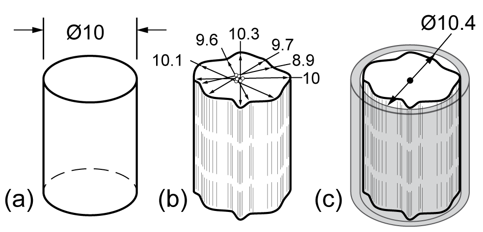
Figure 2. Conventional determination of size and center.
Similarly, it is common practice to determine the center of a geometry by halving a measurement between opposite points or for a series of measurements. Unfortunately, this yields a cloud of center points rather than a single true center. Again, each set of opposite points will yield a different, non-repeatable center (Figure 2b). Functionally, the center of the equivalent perfect cylinder (Figure 2c) is repeatable and of importance when designing mating components. The underlying issue is that conventional dimensioning does not consider the form errors in a feature, and there are no conventional tolerances for form.
Orientation and Angles
Machinists understand that conventional tolerancing does not effectively deal with orientation. For example, consider a peg intended to be perpendicular to the top surface of a plate (Figure 3a.i). Assuming that line-to-line contact would fit, the Ø10 peg should fit into a Ø10 hole perpendicular to the surface of a mating plate while the faces of the two plates contact fully (Figure 3a.ii). Unfortunately, no manufacturing is perfect, so even a perfectly sized peg will be at an angle to the first plate’s surface (Figure 3b.i). If we try to engage the Ø10 hole in the mating plate, the parts will fit together, but the plates will not mate flush (Figure 3b.ii). With conventional dimensioning and inspection philosophies, the size and location of the peg would be measured, but the orientation of the peg would rarely be inspected unless it is visibly not perpendicular to the plate surface. The typical resolution for this issue is to rework the hole until it allows the peg to engage in the hole (Figure 3c.i) fully and the plate faces to mate (Figure 3c.ii).
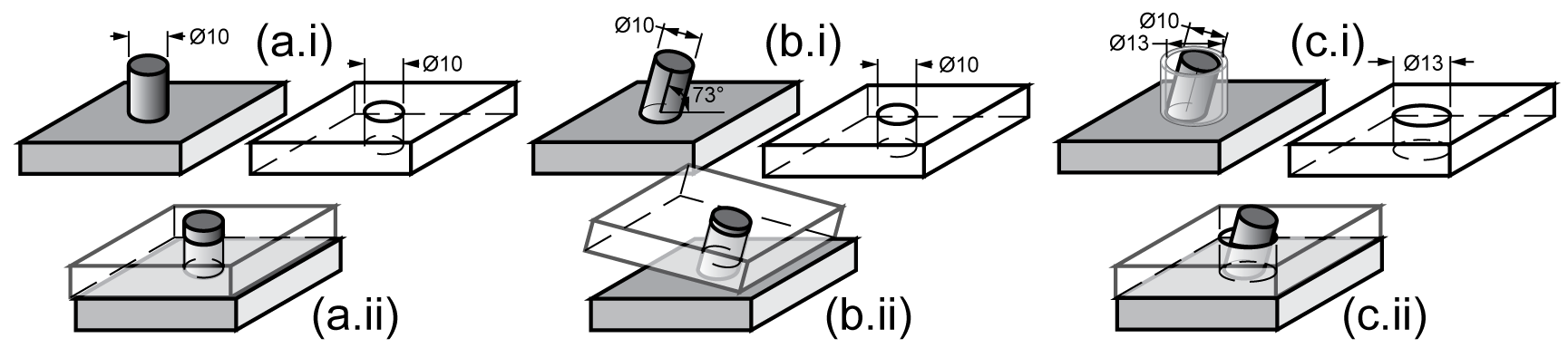
Figure 3. Mating conditions.
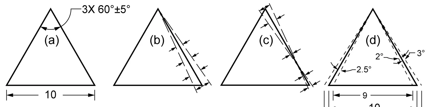
Conventional angular tolerances (± degrees) present two problems of interpretation; wedge-shaped tolerance zones and how to distribute the tolerance. First, consider an included angle between two sides of a triangle (Figure 4a). Angular tolerances create wedge-shaped tolerance zones (Figure 4b). Notice that the width of the tolerance zone increases as you move further away from the inflection point of the tolerance zone. This means that the longer the surface, the greater the allowable error. Now, consider that the toleranced angular dimension applies to all three vertices of the triangle. The result is that the inflection point of the tolerance zone wedge can be at either end of any side of the triangle. This is a valid interpretation of the tolerance callout because no standard exists to interpret conventional tolerances. Furthermore, the inflection point can be anywhere along the side of the triangle, resulting in even more confusing but valid interpretations (Figure 4c).
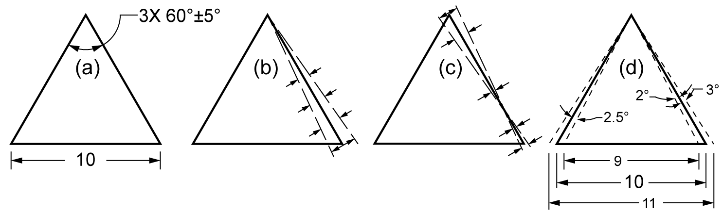
Figure 4. Conventional angular tolerance.
One of several valid interpretations of tolerance distribution for this angular callout is shown (Figure 4d). The tolerance can be assigned to one side or the other. It can be distributed equally or unequally between the two sides. Again, there is no standard by which to interpret this callout.
Tolerance Accumulation
With conventional dimensioning and tolerancing practices, tolerance accumulation is sensitive to how you lay out the dimensions and the tolerances applied to each dimension. Two-dimensional layouts are shown in Figures 5 and 7 (top graphs) to demonstrate the issues of tolerance accumulation. For each layout, the tolerance zone on each feature in the dimension path is provided for visualization (Figure 6 and 8, bottom graphs). In addition, the tolerance (A, C respectively) on the length of the center horizontal section will be determined.
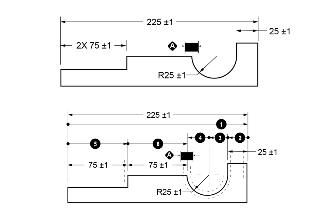
Figures 5 and 6. Dimension layout A (top) and tolerance zones and vectors for layout A (bottom).
For Layout A (Figure 5), there are two dimension-vector paths from the left side of the part to the right end of the center horizontal segment; these are designated A1-2-3-4 and A5-6 in Figure 6. For tolerance analyses, tolerance values add together and do not cancel each other out.
Tolerance A1-2-3-4 = (±1)225 + (±1)25 + (±1)R25 + (±1)R25 = ±4
Tolerance A5-6 = (±1)75 + (±1)75 = ±2
Clearly, the results conflict, which means that the specification is invalid.
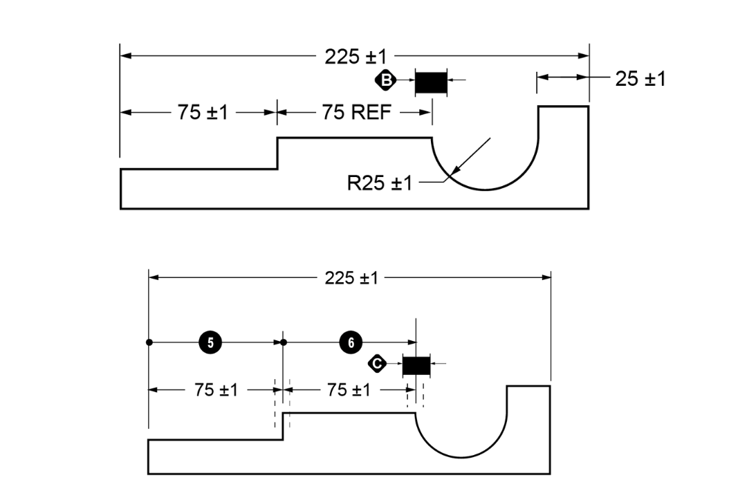
Figures 7 and 8. Dimension layout C (top) and tolerance zones and vectors for layout C (bottom).
For Layout C (Figure 7), the length of the far-right horizontal section is provided as a reference dimension. The tolerance applicable to the location of the right end of the center segment is: C5-6= (±1)75 + (±1)75 = ±2 (Figure 8).
Though both dimensional layouts A and C are valid, comparing tolerances A and C establishes that the feature’s tolerance depends on the dimension layout.
Now that we understand the issues with conventional tolerancing, we can look at how ASME GD&T addresses them in “Part 2: Using Geometric Dimensioning and Tolerancing (GD&T) to Resolve Tolerancing Issues” in the next issue of MMT.


Related Content

How to Eliminate Chatter
Here are techniques commonly used to combat chatter and guidelines to establish a foundation for optimizing the moldmaking process.
Read More
Mold Design Review: The Complete Checklist
Gerardo (Jerry) Miranda III, former global tooling manager for Oakley sunglasses, reshares his complete mold design checklist, an essential part of the product time and cost-to-market process.
Read More
Plastic Prototypes Using Silicone Rubber Molds
How-to, step-by-step instructions that take you from making the master pattern to making the mold and casting the plastic parts.
Read More
Revisiting Some Hot Runner Fundamentals
What exactly does a hot runner do? If you’ve been in the injection molding industry for any length of time, you might think the answer is obvious, but it is not.
Read MoreRead Next

It Starts With the Part: A Plastic Part Checklist Ensures Good Mold Design
All successful mold build projects start with examining the part to be molded to ensure it is moldable and will meet the customers' production objectives.
Read More
How to Manage Wall Thickness Changes in Your Mold Design
To ensure even filling and cooling, consider wall section transitions, corners and fillets, ribs and bosses, lip and rim designs and CAE flow simulation software.
Read More
Get the Most from Your Tooling Investment
Alignment, mold protection, tonnage distribution and injection control are the main elements in the molding machine that could affect your tooling investment.
Read More