This month we delve into the intricacies of bump bending and go back to basics with air forming, reviewing the relationship between the die opening, the inside bend radius, and the material thickness.
Both topics reveal how subtle and complex bending can be. Regarding the bump bend, what works for gauge material might not work for plate. And when it comes to predicting the inside bend radius in air forming, different material from different suppliers can lead to very different results.
Depth of Penetration for Bumping
Question: I recently purchased a copy of your book, Bending Basics. I have a question on bump radius bending, which you cover in Chapter 44, specifically regarding the formula you use for the approximate depth of penetration into the workpiece.
I need to bump-form 0.125-in.-thick material to a 30-degree angle (as measured from outside of the bend) with a 26-in. radius. I’m having trouble applying the equations you spell out in your book: arc length of inner radius = 2πr × (degrees of bend angle/360), with r equaling the bump-formed inside radius. Plugging in the numbers, I get a 16.613-in. arc length.
Assuming 2 degrees per bend, I need 15 bumps to achieve a 30-degree external angle (30/2 = 15). This means the distance between the bumps (the radius pitch) needs to be 1.107 in. (16.613/15 = 1.107). I double that to get my ideal die width of 2.214 in. Finally, I calculate the approximate depth of penetration: [(Die width/2) + Material thickness – 0.02. When I plug in the numbers, I get a depth of penetration of 1.212 in. That depth of penetration does not make sense to me. I’m hoping you can tell me what I’m doing wrong!
Answer: There are several reasons why this is not working out for you. First, the process works best for materials 16 ga. and thinner—it really isn’t valid for the material thickness you’re working with. This doesn’t mean that bump radius bends aren’t possible in thicker materials. They can work, but usually do not turn out very well because of the large die openings they require.
The second and most significant reason is the size of the inside radius, 26 in. A large radius is better suited to roll rather than bump-form on a press brake. Why? Because even if your bend is only 2 degrees at every “bumped” bend line, the distance (radius pitch) is too great between each individual bend. A bump-formed radius involves a series of small flats between each bend, no matter how close the distance is between the bend lines. Nonetheless, the outside surface of the bend should look and feel smooth. When bump forming with a large distance between bend lines, that smooth look becomes harder to achieve.
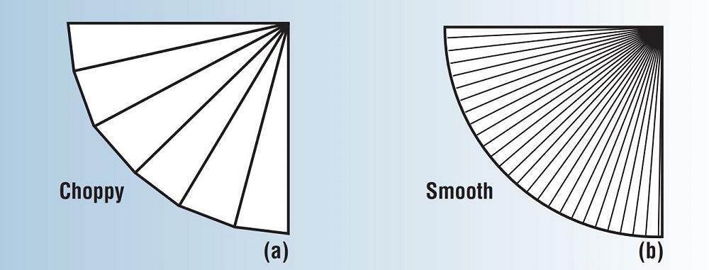
In your case, with 1.107 in. between bend lines, the outside surface will not be smooth (see Figure 1). Instead, you’ll end up with a series of flats 1.107 in. apart. Bumping a radius of 26 in. will require many more bends for a smooth outside surface. If you were to bump each bend a half a degree instead of 2 degrees, you would need to bump 60 individual bends to produce a bumped angle of 30 degrees. However, the radius pitch between each bend will be reduced to 0.223 in., a reasonable value.
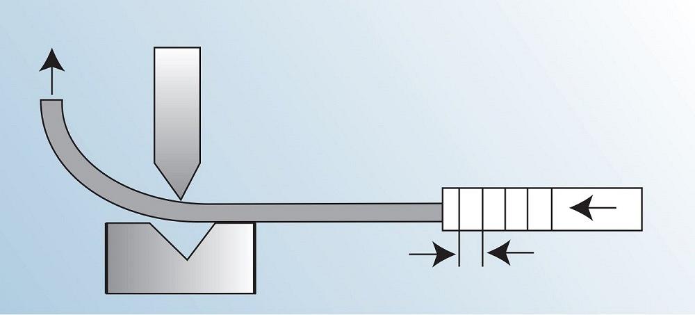
For the die width, you will typically be doubling the radius pitch. Doubling the radius pitch should give you a die opening slightly smaller than an optimal opening. This smaller die opening allows the material you are forming to lay across both shoulders, stabilizing the bend location (see Figure 2). In the example just cited, the die opening would be 0.446 in., giving you the choice of using a 0.472-in. or a 0.394-in. opening.
Considering your material is 0.125 in. thick, an optimal die opening would be 0.709 in. and require a tonnage of about 1.07 per in. for 60,000-PSI-tensile-strength steel. Drop the die opening to 0.394 in., and your tonnage nearly doubles, jumping to 1.959 tons per in. This increased tonnage may or may not be an issue for you, but it will no doubt mark up the material by putting creases into what should be a smooth outer surface.
FIGURE 1. The radius pitch (distance between the bend lines) determines how choppy or smooth a bump bend will be.
More than four times larger than a 0.394-in. die., your 2.214-in. die opening is way larger than required for a bump radius bend. It’s also why your approximate depth of penetration numbers seem way off.
Before giving you an example of how this process works, consider one key point: The value you’re calculating represents the penetration value where the zero point is at the bottom of the die.
Let’s look at how these calculations work for the material thicknesses suited for this type of operation. Here, we will run the calculations for a piece of 16-ga. material with a 4-in. inside bend radius at 90 degrees of bend angle.
Arc length at the inner radius = 2πr × (degrees of bend angle/360)
Arc length at the inner radius = 2π4 × (90/360) = 6.238 in.
Degrees of bend/Degrees per bend = Number of bumps
90/2 = 45 bumps
Radius pitch (distance between bumps) = arc length at inner radius/number of bumps
Radius pitch = 6.238/45 = 0.139
Ideal die width = Radius pitch × 2
FIGURE 2, The workpiece needs to sit squarely across the die shoulders to keep the part square against the gauging stops.
Ideal die width = 0.139 × 2 = 0.278 in.
Approximate depth of penetration = (Die width/2) + Material thickness – 0.02
Approx. depth of penetration = 0.139 + 0.062 - 0.02 = 0.181 in.
As you can see, while your calculations were correct, they just were not functional for the product you were trying to bump. While you could, in theory, create the 30-degree bumped radius using the data you calculated for a 2-degree bend angle at each bump, it would not be smooth. And if you went to a half a degree of bend angle in a smaller die using 60 bends, the application would be very time-consuming and likely impractical. Besides, the excessive tonnage load could damage the part surface.
How the Die Opening Affects the Radius
Question: I would like to know the relationship between the die opening and inside radius. For instance, say I’m forming 0.060-in.-thick material over a 0.472-in. die to 90 degrees. What will my radius be?
Answer: You are looking for the 20% rule, which can be used to approximate what an air-formed inside bend radius will be. It’s just a title for a rule of thumb, a starting point, and you need to be prepared to deal with errors. Most errors we encounter stem from the material. The modern press brake’s repeatability is in microns, measured in one-millionth of a meter, but the material has all kinds of tolerance zones. Take a piece of A36 16-ga. material. The thickness tolerance range for 16 ga. is between 0.053 in. and 0.067 in., a variation of 0.014 in. Yield strength starts at 36,000 PSI but can be as high as 43,000 PSI, a 13% difference. Why am I telling you this? It is because when we look at the 20% rule, we need to realize that the answer you calculate will never be perfect.
Now, on to the rule itself. The 20% rule spells out how the air-formed radius is created in various materials. In air forming, the radius forms as a percentage of the die opening:
304 stainless steel: 20% to 22% of the die opening
60-KSI-tensile-stregth cold-rolled steel (baseline material): 15% to 17%
5052 H32 aluminum: 10% to 12%
You can start with the median percentage—21% for 304 stainless, 16% for 60-KSI cold-rolled steel, 11% for 5052 H32 aluminum—then adjust from there. What if you’re forming a different material? That’s easy. Just compare the tensile strength of the new material to the percentage used (16%) for our baseline, 60,000-PSI-tensile-strength material. So, say you’re forming material that has a tensile strength of 120,000 PSI. In this case, you’d determine the percentage as follows:
Percent of die opening for air-formed radius = 0.16 × (Material tensile strength in PSI/60,000)
Percent of die opening for air-formed radius = 0.16 × (120,000/60,000) = 0.32, or 32%
This is where the relationship between the inside bend radius and the die opening is established, assuming you’re using a die opening appropriate for the thickness. (Editor’s Note: For more on this, search for “die selection for the press brake” on TheFabricator.com.) Assuming your die selection is as close to optimum as possible, you multiply the die opening by the material’s median percentage. For our A36 example, that’s 16%. This is how you’d apply it to your 0.472-in. die opening:
0.472 × 0.16 = 0.075-in. inside bend radius
Change the percentage value in the calculations if the numbers are small or large. You will find that the percentage values are reasonably accurate, particularly if you stay with a single supply house for your material. If you use multiple supply houses, it would be best practice to use the median percentage value for any calculations you make. Once you find the appropriate percentage and multiply it by the die opening, you use that value to calculate your bend allowances and bend deductions.
One last thing: The 20% rule applies only to air forming. Bottom bending and coining stamp the radius of the punch nose into the material, so the die opening will not affect the inside bend radius.
The Fabricator is North America's leading magazine for the metal forming and fabricating industry. The magazine delivers the news, technical articles, and case histories that enable fabricators to do their jobs more efficiently. The Fabricator has served the industry since 1970.