


Press Brake Automation Sales Manager
Historically, for robotic press brake bending to make economic sense, a job needed to be of a certain volume in a metal fabrication shop. That, however, is starting to change across the industry.
Even today, press brakes can spend surprisingly little time actually bending parts over an eight-hour shift. Sometimes, the issue stems from larger operational inefficiencies, like unavailable material, misplaced tooling, or an unexpected employee absence. Many times, problems stem from a lack of information. Perhaps a part was designed without the right tooling in mind, so the brake operator or supervisor is forced to accommodate, forming multiple tryout parts to get the bend program just right.
Offline bend programming changes the game. Before any bend program reaches the floor, a bend simulation verifies that, yes, the operator should be able to form the part with available tooling without collisions. For certain jobs, adaptive bending technology even accounts for material inconsistencies like grain direction or thickness variation. The brake under-bends the material, measures the angle, then completes the air bend with precision.
Add the press brake’s ability to change tools automatically, and you change the forming department dramatically. No longer must the machines produce large batches to “save on setup.” In fact, the entire department can move closer to single-piece flow and even kit-based production. Work-in-process (WIP) plummets along with lead times.
All this has made the forming department more flexible than ever, except for one problem: the lack of people. A press brake can’t run without an operator—unless you robotize the operation. Still, there remains the problem of flexibility. Historically, robotic press brake cells haven’t been known for their ability to adapt. That, however, has started to change.
Offline bend simulation has transformed the nature of manual bending, and it’s now doing the same for the robotic press brake. Combine offline simulation with automatic tool change, evolving gripper technology, and a strategically designed bending cell, and the automate-or-not decision changes. The robotic press brake is finally getting flexible.
Talk to many shop owners and forming department supervisors who dive into robotized brakes, and they’ll tell you they automate forming for only certain parts. A small robotic brake might form tiny parts that are monotonous and (even worse) unsafe for a person to bend manually. A large robotic brake forms large, heavy parts that would be back-breaking for operators to form manually.
For most parts, though, the whether-to-automate question often comes down to volume, mainly to amortize the initial setup. If an operator needs to spend time with a teach pendant to carefully bring the part through every step of forming, the job needs some level of volume to justify all that work.
Then comes the challenge of gripping. Some automated cells could have a row of gripper end effectors lining the perimeter. Designing all those grippers ensured a bending cell could form a variety of parts, but the process took time and added numerous complications. Here again, volume would dictate the decision to automate. The cell could be designed to run small batches or even kits, but to justify all the engineering, integration costs, and setup time, that automated cell needed to produce many kits over a certain period.
This remained true even if everything were first simulated offline. This minimized the time setup personnel spent on a teach pendant, but simulation and programming still took time and resources. People who (ideally, at least) know their way around the press brake now spent a lot of time in front of a computer screen in the office. Offline programming didn’t disrupt production, but still, a programmer’s time isn’t free.
To truly automate a high-product-mix forming operation, it isn’t enough to automate the setup, changeover, and part manipulation on the floor. Fabricators need to automate the offline programming and simulation (see Figure 1). That is, the software develops instructions for the entire cycle, from the presentation of cut blanks to the removal of formed parts, stacking them onto a pallet or placing them into a bin. The programmer then reviews what the software has developed, adjusts certain aspects if needed, then sends that program to the floor.
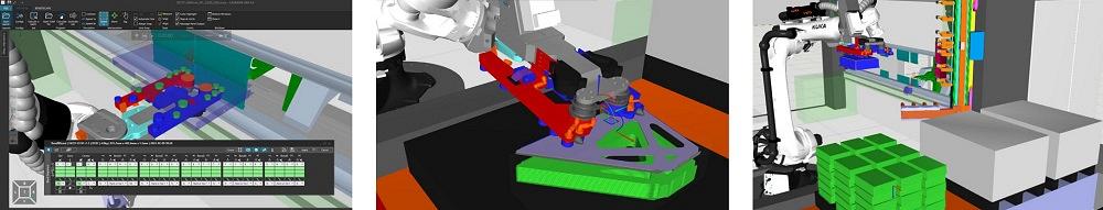
FIGURE 1. Software simulates the complete robotic bending cycle, from blank picking to part stacking. The software also can calculate the gripper position and the best cups to grasp the part.
No longer buried in the minutiae of robotic bending, programmers now can delve more into part flow strategy. Once this happens, a fabricator can automate the bending jobs that make the most sense for overall throughput.
When it comes to minutiae, robotic bending isn’t lacking. Consider first how parts are presented and gripped. The program needs to know how many of which part can be placed on each pallet securely and consistently. Once the pallet arrives at the bending cell, a QR code is scanned, notifying the production control software that the pallet is staged and ready to go. That code also calls up the appropriate program.
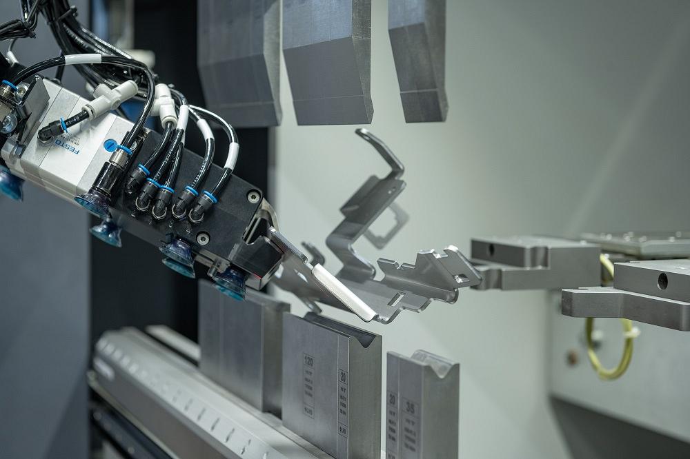
Next comes the actual part gripping. A robot might grip a part, head to a regripping and centering table, where it releases and regrips the piece to ensure it’s gripped in the proper position (see Figure 2). To eliminate that first step, some bending cells use pallets that present parts at an angle, centering the pieces before the robot grips them. This means the part needn’t be referenced at the centering and regripping table before the first bend.
Then comes the gripping itself. Cutouts within the blank need to be accounted for, of course, but so does the nature of the material surface. Suction cups securely handle magnetic and nonmagnetic materials, with “smart” grippers activating and deactivating certain cups to manipulate the work. The cups themselves, however, need to be designed to accommodate different sheet metal surfaces, including oily ones. When grasping the piece, some systems integrate an air-blowing system that clears the surface of excess oil and other debris before the cups grasp and obtain a secure hold on the surface.
Next comes the peeling process—that is, when the robot “peels” a single sheet off the pre-centered stack of blanks. The robot moves in a multiaxis motion while a magnetic or brush-based system ensures the blanks separate, to prevent double-picking (particularly critical for thin sheets). The robot then carries the blank to a thickness measurement device to verify it has just one piece (see Figure 3).
Next comes the bend cycle itself, one of the most involved and complex tasks an articulating robot arm can perform. As a baseline, the system must verify that the correct and sufficient number of cups are activated to hold the part securely. This starts with the initial grasps and continues throughout the bending cycle.
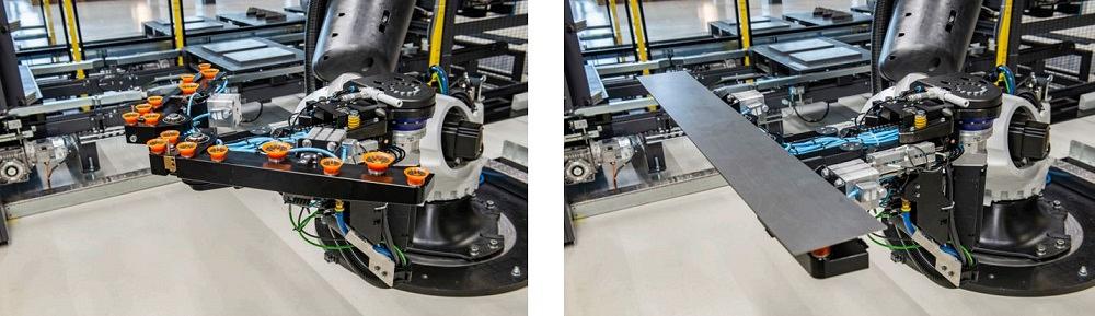
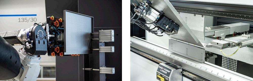
Gripper technology plays a key role here as well. Some grippers integrate multiple gripping methods, including clamps and suction cups. And today, some grippers actually alter their surface area throughout the bend cycle. At the start of the cycle, the end effector might need to grip a large gripping surface. Here, “wings” of suction cups pivot outward to expand the gripper’s reach (see Figure 4). Mid-cycle, the gripper retracts its wings and, if needed, can pivot around, giving an additional axis of motion to manipulate the work from one bend to another, mitigating the need to regrip while also avoiding collisions with tooling, backgauges, and anything else that could alter the workpiece’s position on the gripper. It’s a subtle science.
Just as gripping is a subtle science, so is regripping. Because the gripper can swivel 360 degrees, it needn’t release the part throughout the entire job. It positions the panel for the first bend, supports the flange as it swings upward (to prevent sheet deflection from affecting bend accuracy), removes the work after the toolset releases the bend from pressure, then rotates and moves immediately to the next bend—no regripping required.
Now picture a smaller part with four bends, only this time, part geometry attributes (such as interior cutouts or the bend location) require the gripper to reposition itself between bends. That said, because this is a small part, regripping can actually occur at the machine. The gripper follows the flange upward for the first bend, remains gripped as it removes the workpiece from the tooling, then rotates the piece for the second bend and slides it over the die and against the backgauge. The punch descends until it pinches the metal. This effectively “clamps” the material in a known position and allows the gripper to ungrip and reposition itself in a new location. Once it’s secure, the bend cycle commences and the gripper follows the flange upward.
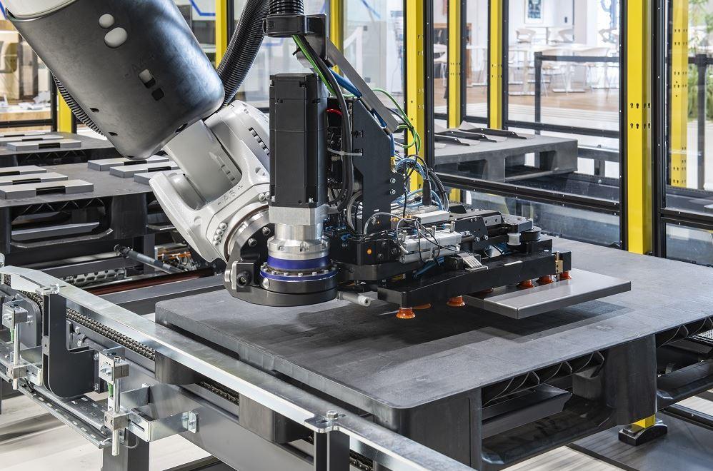
Now picture that same part, only larger. If the robot performed the same gripping strategy, physics would get in the way—specifically, deflection. All would be well until the robot positioned the part for the second bend. The tooling would clamp the work, the gripper would release, and the flange would bow under its own weight, hindering positioning and bending accuracy for the rest of the bend sequence. In these cases, the robot needs to take larger parts to the regripping station, where it regrips and continues with subsequent bends (see Figure 5).
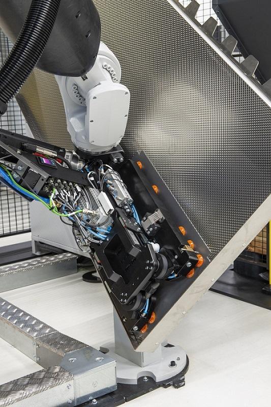
FIGURE 2. A part is brought to a centering table to ensure the end effector is gripping the part in the proper position.
Next comes parts offloading, and again, it’s a subtle science. Stacking rectangular panels is usually straightforward, with a slight rotation of each part ensuring the stack remains stable as it’s transported downstream. Offloading small parts into a bin is similarly straightforward. Some large panels might even be stacked vertically.
Today, algorithms have successfully automated most of the programming for stacking, except for extremely irregular parts. Research is in the works to develop algorithms that automate the programming of complex parts stacking, with parts being “nested” on top of each other in specific orientations, all to ensure a stable stack. For now, programmers can manually develop the stacking program of irregular parts within the simulation software before testing the stacking concept on the floor.
Such stacking remains one of the last programming tasks that isn’t automated. Everything else—tool selection, bend programming, robot and gripper movements, regripping strategies, part presentation—is now handled by software.
This in turn changes the nature of what it means to be a robotic press brake programmer and supervisor. Instead of focusing on all the bending minutiae, they focus on part flow, what works best for automation, what works best for manual operation, and which jobs could benefit from both.
Imagine you’re a press brake supervisor managing a bending department with a collection of manual press brakes alongside one automated bending cell with automatic tool change. That automated cell is set up for high-mix production, with a collection of input and output pallets, each of which is designed to handle different parts. Moreover, that cell operates with the bed at floor level, so it can be used in “manual mode,” with the robot locked and out of the way and an operator manipulating pieces through the bend sequence.
All this gives you a host of options, and the decision-making starts in punching and laser cutting. For instance, say a workpiece with an interior cutout really can’t be bent automatically; the gripper simply doesn’t have the surface area it needs to grasp and support the part, and the piece is too large to be supported by the gripper’s edge clamps.
In this case, the solution might be in laser cutting. Instead of cutting the interior geometries on each part profile, the laser can cut a kerf with a series of microjoints. This gives the bending robot’s gripper the surface area it needs to grasp, after which that interior slug microtabbed in place could be removed.
Let’s say that same part requires the gripper’s edge clamps to grasp the piece during the final bends—yet, again, what if the part doesn’t have enough surface area to make this happen? Here, adding a sacrificial tab—either cut with microjoints or punched with a tool to create a snap-apart edge—could be an option.
What about a piece too small for the company’s robotic press brake to form? One option is to use a robotic brake with end effectors having suction cups and pinch clamps designed for tiny parts. That’s not the only option, though.
Imagine a series of small brackets together in a “mini-nest” on a punch press with automated parts offloading and stacking. That mini-nest serves a dual purpose: It gives enough surface area for the small blanks to be stacked automatically after punching and for another robot to grasp the pieces (still in the mini-nest) for bending. Only after bending do the pieces require manual intervention, as operators snap the formed brackets apart before they’re sent to finishing and assembly.
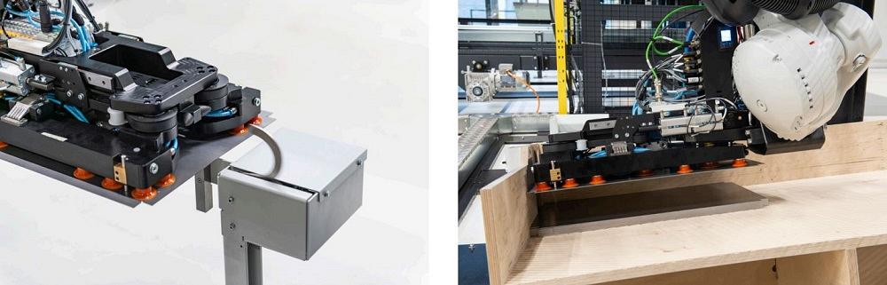
FIGURE 3. A gripper “peels” the part from a stack that, presented at an angle, pre-centers the parts, so the robot needn’t visit a centering station before bringing the part to the work envelope. The piece is then brought to a thickness measuring device, which checks for double-picking.
This is where big-picture, business-wide thinking comes into play. Say the assembly department has a large kitting area where a half-dozen employees sort through batches and kit together the pieces assemblers need. With flexible cutting and bending upstream, could part flow be changed to simplify or even eliminate the need for that kitting area?
At the bending cell, multiple input and output pallets could be sequenced for more efficient kitting directly after forming—all while taking tool changes into consideration (see Figure 6). Software can sequence different parts in a kit that share common tooling or allow for quick automatic tool changes.
Each pallet within the automated cell still carries stacks of one part, not a kit of different parts, which gives the system flexibility should part flow from upstream vary unexpectedly. (What if only four pieces out of a five-piece kit are available for the robot to bend?) That said, the system can work with multiple pallets. As pallets are removed from the cell, they flow downstream in small batches that can be kitted together quickly.
What if one part can be formed almost entirely by the robot, except for the final few bends? The robot might have trouble gripping, or the final bent geometry might be difficult to stack. In this case, the robot could perform the most time-consuming portion of the forming job unattended overnight. When operators arrive in the morning, they retrieve the stack and perform the final few bends manually, either at a manual brake or with the robot bending cell in manual mode. (Which to choose would depend on the capabilities and available capacity of machines in the bending department.)
It might sound odd to automate only a portion of a job: Why not just form the job manually in its entirety? The forming job could be challenging and difficult to handle, at least until the final few bends. Also, more often than not, bending personnel probably aren’t available, so the shop simply must automate to meet demand.
Everyone knows the unfortunate reality: Experienced press brake operators are tough to find. The idea behind flexible bending automation is to make best use of the bending talent fabricators have.
Robotic press brakes can process a wide range of pieces, from simple enclosures to work requiring complex incremental (bump) bending, with the robot end effectors safely guiding the work through each bump. But sheet metal forming is an extraordinarily complex process, and not every piece is suitable for the robot. Some pieces might require special tooling. Robotic and gripping technology has come a long way, but they can’t solve every forming challenge. Manipulating or removing a piece after the final bend might be difficult. Parts that emerge from a punch press with extruded holes or other forms might make stacking difficult and unreliable. Some forms made on the punch are easily stackable, but others are not, depending on their size, number, and where they’re placed on the blank profile.
Manually forming these jobs might still be the best option, and they still can offer training and experience for rookies and shop veterans alike. After all, a part that’s difficult for a robot to grip and stack isn’t necessarily difficult for a person to form manually.
At the same time, bending automation gives personnel the chance to think strategically. What parts do assemblers need and when? What’s the best way to present it to them? Where does kitting occur, and where could it occur? Does it make sense for small parts to be snapped apart after bending, especially if those edges aren’t exposed and don’t require deburring?
Most critically, no longer is automated bending on the press brake limited to high-quantity work, though with a few exceptions. An operation might choose to automate a challenging job with special tools, gripping, and “nested” stacking of unusual shapes. These jobs still require some programming time, so quantity will remain a factor in the automate-or-not decision.
Outside of these special cases, though, programming can occur in minutes, grippers are flexible, and tool changes are automated. Put all these advancements together, and you create a robotic press brake operation where part volume is no longer the deciding factor.


The Fabricator is North America's leading magazine for the metal forming and fabricating industry. The magazine delivers the news, technical articles, and case histories that enable fabricators to do their jobs more efficiently. The Fabricator has served the industry since 1970.
start your free subscription
Easily access valuable industry resources now with full access to the digital edition of The Fabricator.

Easily access valuable industry resources now with full access to the digital edition of The Welder.

Easily access valuable industry resources now with full access to the digital edition of The Tube and Pipe Journal.

Easily access valuable industry resources now with full access to the digital edition of The Fabricator en Español.
In this episode of The Fabricator Podcast, Caleb Chamberlain, co-founder and CEO of OSH Cut, discusses his company’s...


