Experience of engineer plays a major role in PLC troubleshooting.
1. Keep Spare parts ready:
In general, keep 10% spare parts ready for the number of that part used.
So that if a part malfunctions, you need not search for a replacement at the eleventh hour.
2. About Fuse:
If you replace the fuse and if it blows again then, the problem may be that the module’s output current limit is being exceeded or the output device is shorted.
3. Ground Loops
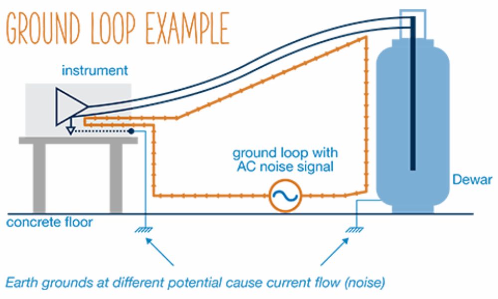
When two or more electrical paths exist in a ground line, it is called a ground loop.
For example, in the figure above, at the chassis or device enclosure, transducer and transmitter are connected to ground. The transmitter is connected to an analogue input card through a shielded cable. The shield connects to both chassis grounds. So, it creates a path for current to flow from one ground to another since both grounds have different potentials. The current flowing through the shield would induce magnetic fields in the signal transmission.
This could create interference. Hence, the shield should be connected to ground on only one side of the chassis, preferably the PLC side so that this difficulty will be solved.
How to check whether a ground loop exists?
Observe the diagram below.

Disconnect the ground wire and measure the resistance between ground wire and ground. Measure resistance between these 2 using ohmmeter.
If it shows large resistance it means that no ground loop problem is there.
If it shows less resistance it means that the ground loop problem is there.
4. Diagnostic PLC indicators.
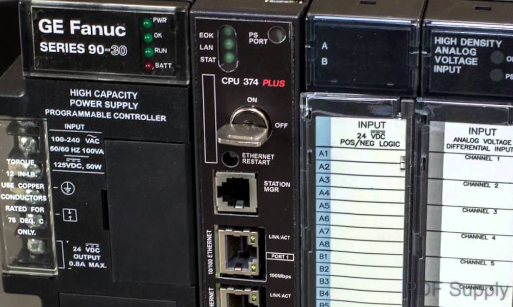
LED status indicators provide useful information about field devices, wiring, and I/O modules.
Power LED becomes ON if PLC is receiving sufficient power.
Similarly LED indicator for input terminals becomes ON if the input signal is received properly.
- If necessary check supply voltage, input device and wiring using a digital multimeter.
- If the PLC has developed a result to turn ON an input terminal, then its indicator LED will become ON.
- By monitoring using programming software, you can come to know which output terminal is supposed to be ON. Using multimeter you can check output wiring and power supply.
- Ensure that an output device should not draw current more than the current capacity of the output terminal.
- Also, the switching frequency should match. In the case of connecting the input device like encoder etc to the input terminal, pay attention to switching frequency of input terminal. Refer hardware manual of PLC to know the switching frequency capacity of normal inputs and high-speed inputs.