Eight frequently-neglected VFD parameters to optimize
Recognizing variable frequency drives (VFD) parameters such as thermal current, pulse-width modulation and more can help engineers get better performance for many different applications.
Learning Objectives
- Learn about the eight most common variable frequency drive (VFD) parameters that are often overlooked.
- Understand how addressing these parameters can help manufacturers improve operations.
- Learn about how engineers can improve user experience with graphical displays.
Over the last century, electric motors have become ubiquitous for powering a variety of industrial devices, including pumps, fans, and compressors. In the last few decades, variable frequency drives (VFDs) have emerged as a powerful, and now common, tool for reducing energy consumption and optimizing control of electric motors.
When setting up VFDs for industrial automation, its likely engineers worked with electrical contractor to ensure each VFD was adequately controlling its respective motor during commissioning. That said, electrical contractors are often not experts in optimizing the drive to the specific motor and application needs. Most modern VFDs are complex control devices include many parameters that can be fine-tuned to bring even more benefits to an application.
Eight variable-frequency drive parameters for industrial automation
There are eight VFD parameters that often are not addressed during installation and often can be optimized to bring a number of improvements to the motors.
For all the settings discussed in this series, first verify the parameter matches what is listed in the manufacturer documentation and paying particular attention to engineering units.
VFD parameter 1: Thermal current
The thermal current is a parameter that indicates the maximum allowable current, which is different than full load amps (FLA). While FLA is the rated power and indicates the maximum amps allowable for the motor long term, thermal current indicates a higher amperage that can be applied briefly, allowing the VFD to safely apply more than the motor’s standard rated power.
The thermal current setting informs the VFD how much “extra” power the motor can handle and still operate without a thermal failure. When this limit is exceeded, the VFD can trigger a fault before a motor overload occurs, protecting the motor from thermal failure. When configuring the drive parameter for motor current, users can find the FLA and motor service factor (SF) on the motor nameplate. Multiply these two values to calculate the thermal current in amps.
VFD parameter 2: Pulse-width modulation (PWM)
Every VFD powering an ac motor works by converting line ac power to dc, which the VFD then modulates into an ac waveform. This modulation is done by rapidly pulsing the DC power – turning it on and off – to create an ac wave. The VFD adjusts the wave’s amplitude and frequency to spin the motor at the desired speed. The pulse-width modulation (PWM) switching frequency parameter regulates these pulses and can be adjusted by changing the number of pulses used to create the ac powering the motor.
When PWM is not optimized for the motor and application, the dissipation of the heat produced by the motor and the drive is not balanced. If the PWM is too low, the motor will heat up faster, which is indicated by the motor screeching. Eventually, this can lead to issues with insulation breakdown and/or bearing pitting. A high PWM requires the drive to work harder, eventually overheating the drive and shortening VFD life.
An elevated PWM can also increase the development of reflective waves between the motor and the drive, which can cause increased current induction in the motor shaft, resulting in bearing pitting in the motor and grounding faults in the drive. By correctly fine-tuning the PWM, users can balance heat displacement and extend the life of the motor and the drive.
VFD parameter 3: Deceleration time
Deceleration time is the parameter that determines how long the VFD will take to slow down the motor. A longer deceleration time will lead to a longer ramp down to fully stop the motor. While many installers know to optimize acceleration time to prevent issues with over-current at start-up, the deceleration time tends to get overlooked.
Adjusting the deceleration time is important for preventing an over-voltage fault that can be created when power is removed from a motor and the inertia from the load continues to spin the motor. This rotation causes the motor to generate electricity, which is fed back into the drive, causing it to fault. In this case, an appropriate deceleration time will decrease the magnitude of electricity created by the slowing load and prevent a fault. For example, if users have a motor controlling a fan and it takes 10 seconds to decelerate and stop the fan, the drive should be programmed with this deceleration time to extend the life of the motor. Please note though, if a quick stop is required for process or safety reasons, additional hardware may be required and appropriate experts should be consulted.
VFD parameter 4: Minimum operating speed
The minimum operating speed is a speed setpoint, typically calculated as a percentage of maximum speed, below which the VFD will tell the motor to not run. Since most motors are cooled by an internal fan, which has a speed directly correlating with the motor speed, setting a minimum operating speed is important to prevent motor overheating that can occur at low speeds. For example, if the minimum operating speed is set to 10%, and someone provides a speed reference to the VFD of 5%, the VFD will not rotate the motor. Keep in mind the controls integrator should make sure this is taken into account in the implementation of any interfacing programmable logic controller (PLC) configurations, such as proportional-integral-derivative (PID) algorithms where the drive is controlled by the control variable (CV).

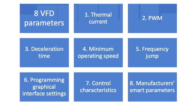
Knowing eight variable frequency drive (VFD) parameters can help optimize motor system operations for automation. Graphic courtesy: Control Engineering; Information courtesy: Applied Control Engineering
VFD parameter 5: Frequency jump
The frequency jump function typically consists of several parameters. The frequency jump parameters each denote a frequency at which the VFD will not run the load. Many mechanical systems have a frequency – or frequencies – at which the system will excessively – and possibly destructively – vibrate. For example, if a system has a resonant frequency of 40 Hz, it would excessively vibrate if the motor were running at 40 Hz, possibly shaking parts loose. By properly setting the frequency jump, the VFD will skip 40 Hz, and prevent these vibrations. While some equipment manufacturers may identify resonant frequencies, they are more commonly found by experience. There may be additional related parameters indicating a band, so there is a range the VFD will not dwell at.
VFD parameter 6: Programming graphical interface settings
Every major manufacturer offers a small programmable LCD human-interface module (HIM) with their drives. While the default settings may be appropriate for some applications, the module is generally programmable to show different values on the display or to customize the user experience. Three of the most valuable settings, display value, display units and password, are covered below, though parameter names may vary by VFD manufacturer.
1. Display value
Most VFD HIMs have a default factory setting to display the motor speed. Some applications are better served by displaying another value. For example, motor power will change in many mixing applications as the viscosity changes. Displaying the power on the HIM will allow an operator to determine how mixed the product is without bringing up a supervisory control and data acquisition (SCADA) display in a control room. The best way to determine the ideal display value is through knowledge of the process, the options, and plant operators’ preferences. Depending on the manufacturer, an operator also could view frequency, current, custom messages, or a calculated value.
2. Display units
The value of the HIM can only be optimized if the right process information is displayed in the right units. In some cases, this is simply changing the display to show the value in metric units, such as liters/min instead of gal/min. In other cases, it may be aligning the value to match SCADA and HMI screens to show percent speed instead of RPM.
3. Password
The password and related settings can be used to limit operation of a VFD from the HIM. While limiting VFD operation might be for security reasons, there also are operational reasons to restrict control of a motor. For example, it may not be desirable to surprise an operator in the control room by turning on a motor from an HIM in the field. Many manufacturers’ password settings can lock out any unauthorized users, while retaining visibility on the display parameters. Determining the best use of these security measures is best done as a collaboration with plant and engineering personnel responsible for safety, security and operations.
VFD parameter 7: Control characteristics, four common control settings
The control characteristics are a group of parameters that help define how the VFD will change frequency and power to meet the programmed setpoints in high-end drives. This can be essential for ensuring the correct amount of torque is applied at the proper time for the application. This is not to be confused with the settings for those setpoints that are always set up during commissioning. Most manufacturers provide several different control characteristic settings to help with the specific application, with the four most common being:
-
Volts per hertz (V/Hz): Controls the magnitude of voltage and current relationship. Good for fan and pump applications where flow is more important than pressure. Will maintain full torque range within about ½ of motor slip (essentially the lag of the stator behind the rotor) but may not be able to maintain torque below 2 Hz.
-
Sensor-less vector (SV): Provides higher starting torque and speed control within ¼ of motor slip. Good for deep well pumps and high constant torque applications (autotune should be used when using this control method).
-
Flux vector (Open loop): Improves upon V\Hz by providing both magnitude and angle control. By sensing the motor flux and orientation, this method provides more precise motor speed and torque control.
-
Closed-loop vector: This method utilizes a motor mounted encoder to provide shaft position and speed back to the drive. By using this method, a motor can develop full torque at zero speed. Ideal for crane and hoist applications.
Some of these interact with each other, and others preclude the use of different parameters. For example, setting torque control settings negates the ability for auto-tune.
VFD parameter 8: Manufacturer-specific “smart” parameters
Today, many VFDs include a variety of “smart” features that can help further improve the efficiency and lifespan of the motor. However, since these features vary from drive to drive, we often see many of these features are underutilized. For example, some drives include sensors to monitor how much power is needed to produce a certain speed. When a drive is first setup a baseline power curve can be established and used to program a maintenance warning if a bearing is wearing and more power is required to produce the same speed.
Some drives may also come with the ability to perform certain actions based on a trigger condition. For example, a drive connected to a pump may sense the pipeline is starting to experience a blockage based on the amount of power required to move the fluid through the pipe. The “smart” drive could be programmed to temporarily increase the power in an attempt to clear the pipe.
When these manufacturer-specific smart features are understood and implemented correctly, energy efficiency improvements and the ability to proactively perform some maintenance tasks is possible. When these features are set in conjunction with the control characteristics discussed above, users can even get more power out of the drive regardless if it’s operating at the low or high end.
Kurt Niehaus is manager of sales and Will Young is an engineer at Applied Control Engineering, a CFE Media and Technology content partner. This article appeared on Applied Control Engineering’s website in two parts. Edited by Chris Vavra, web content manager, Control Engineering, CFE Media and Technology, cvavra@cfemedia.com.
MORE ANSWERS
Keywords: Variable frequency drives (VFDs), discrete manufacturing
CONSIDER THIS
What are the most important parameters you consider for VFDs?
Original content can be found at Applied Control Engineering, Inc..
Do you have experience and expertise with the topics mentioned in this content? You should consider contributing to our CFE Media editorial team and getting the recognition you and your company deserve. Click here to start this process.
Related Resources


