Teardown: What’s Inside a Human-machine Interface (HMI)?
Human-machine interfaces, or HMIs, provide visual process data and allow access to process parameters and diagnostics information. What’s inside these touchscreen displays, and how do they actually work?
Smartphones and tablet computers have propelled touchscreen interfaces into nearly every part of our daily lives. It should come as no surprise then that these screens have found their way into machines and control cabinets on the manufacturing floor. These human-machine interface (HMI) devices are far beyond a simple touchscreen, however. Have a look inside a typical HMI to learn how they are constructed and how you may be able to care for them to extend operational life and prevent accidental damage.
HMI Screen
The immediately obvious exterior of the HMI is the screen itself, with a hardened plastic (and sometimes metal) bezel around the perimeter. This provides a surface from which to secure the screen into a cutout along with a rubber or weatherproof gasket to force a secure connection.

Figure 1. HMI outer frame (bezel) and screen showing wear and tear from years of use.
It can be seen from this image that it is common for fingerprints to find their way onto the screen, and since this outer covering is usually plastic, be sure to follow the manufacturer's policy on cleaning using appropriate chemicals, as glass cleaner may ruin the surface.
Main Control Board PCB
With the back of the plastic case removed, two important items are visible. First is the main PCB that houses all of the communication and processing capabilities. Since this HMI is only a display and input interface, it will not contain connections for any actual I/O devices. Rather, the network and programming ports can be seen which allow it to share data with the central control system. The other important item is the battery, connected via the short red/black wire set on the back cover.

Figure 2. Back cover removal shows the CMOS battery (on the left, still attached to the back cover) and the main control and networking PCB.
HMI Battery Replacement
This battery serves a similar purpose to those contained on typical PC motherboards and PLC CPUs, called a CMOS battery. This retains clock and basic I/O settings for initial startup. That critical information must stay in the memory of the computer even while it’s turned off and removed from power for extended periods of time, and this battery provides the ultra-small current required for such a task.
For computers, this battery may never need to be replaced, since they can last for sometimes up to 10 years, and that could likely outlive the service life of the computer. But a good PLC or HMI should live much longer than the 7-10 year life of a typical coin cell battery.

Figure 3. Coin cell battery, necessary to retain setup information while the screen is powered down and/or unplugged.
Following the manufacturer’s advice, power down the HMI and remove the power supply cable. Although power will be completely removed when the battery is changed, it will usually retain the data for at least a few seconds on its own, so you need to have the new battery close at hand when completing this task.
Access the battery through the panel, most likely the back side. This model has a little hinged door with a small retaining clip, but some models require unscrewing the back cover, just like the picture. Remove the old battery (I advise using a plastic tool), taking care NOT to let it touch any metal nearby. The 3 volts can be enough to destroy other circuits if it makes accidental contact. Replace the battery quickly following the proper polarity (+/-) marked on the battery.
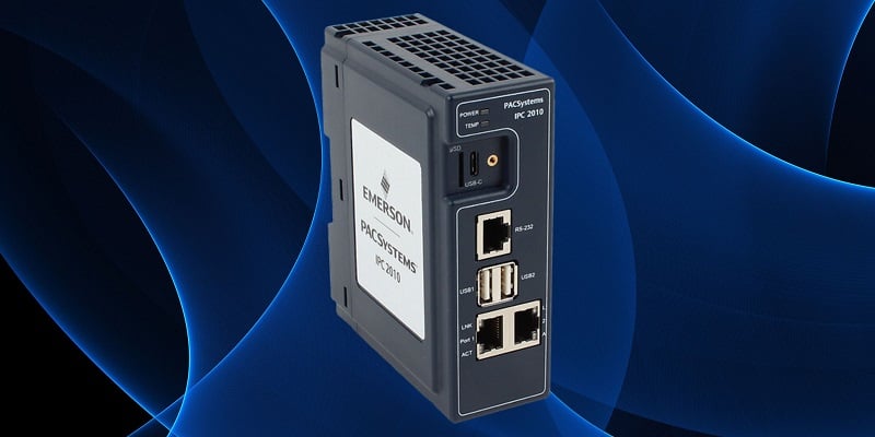
Communication and Networking PCB
This part of the HMI explains itself quite obviously to the experienced engineer. A variety of power and communication ports allow the HMI to network along with control equipment and accept programming instructions from a PC. This means you can expect to find Ethernet, USB, serial, and other ports.

Figure 4. Communication, programming, and the green power header are all present on the main control PCB.
You can’t claim that any piece of an HMI is ‘more important’ than any other part, however, this PCB is critical for operation. Slits and vanes in the back cover allow proper airflow for cooling. Make sure the vents remain open, but at the same time, be sure that excess dirt and contaminants remain far away.
Finally, when performing any drilling or cutting near the HMI (this is common when it’s mounted inside a cabinet door and new button holes must be drilled, for example), never allow bits of conductive metal to fall into the back and touch this PCB. It will almost certainly cause failure.
HMI Touchscreen Components
The remaining sections of the HMI constitute the screen itself. This part is reminiscent of any screen replacement process for a laptop, TV, phone, etc.

Figure 5. With the control PCB removed, the screen driver boards are clearly visible.
Most of these components are not user-serviceable. In fact, due to the adhesive used to attach the thin glass screen to the plastic frame, I resorted to cutting the screw posts with a rotary cutoff tool in order to break down the inner components.
Protective Cover
First, the thin glass screen on the left side below is covered by an equally thin plastic protective cover, shown on the right. During normal operation, the cover protects the screen from dust and dirt, as well as moisture, while still thin enough to respond to the touch input. Do NOT push too hard or use anything other than a finger or stylus. The plastic can easily flex enough that a sharp object will break the glass. Think of your phone, those screen protectors can withstand some abuse, but they aren’t invincible.

Figure 6. The actual screen on the left and the clear plastic cover on the right.
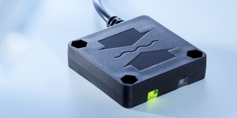
Touchscreen Connector
Fixed to the surface of the screen is a flexible membrane with a capacitive network of conductors. These form an x-y grid of sensitivity, enough to locate the center of a finger or stylus press. This touch screen is connected to the driver boards by means of a thin, flexible ribbon connector, clearly seen in the following image.

Figure 7. Flexible ribbon connector to provide touch capability for the screen
Screen Driver PCBs
The following sequence of images highlights two important parts of the module that actually display the image on the screen.
First is the backlight driver. This power PCB converts a low power input into a high voltage that illuminates a backlight. Usually, the brightness can be adjusted from the HMI settings menu. The input power and control come from the blue wires, and the power output to the lights are through the white/pink wire sets along the top and bottom of the screen.

Figure 8. The backlight illumination power PCB. Inductors on the reverse side create the high voltage output from a lower voltage input.
Finally, the display driver converts the input signal from the main control PCB into the commands that control each pixel to turn on/off and set a color. Once again, this is the same scheme as used for every flat-panel display ever created (CRT displays are a whole different story). Variations exist in how the signal is sent for LED vs. LCD screens, but all will have a similar look and feel.

Figure 9. The actual display driver boards. Note the huge quantity of thin ribbon wires (brown/orange in color) extending to the top and side. The number of wires indicates the resolution of the display, this model being a 640x840 pixel version.
Giving Your HMI a Long, Healthy Life
Be sure to follow instructions for attaching these displays to a cabinet or machine, but beyond the bare minimum, use common sense when working around them. Avoid dirt, dust, and excess moisture around the back side of the panel, especially metallic debris. Never push too hard or abuse the panels, as the glass screen cannot be replaced. Follow the proper instructions for interval and process for replacing the battery.
Take care of your equipment, and it will always be there for you.