


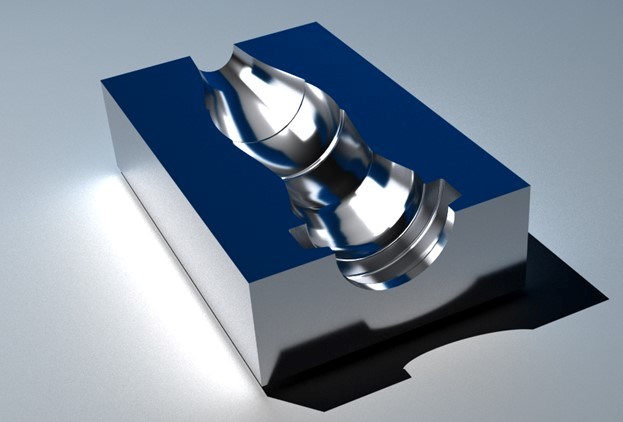
For complex mold machining, like this glass bottle mold, CAD/CAM with innovative toolpath strategies is essential. Photo Credit, all images: BobCAD-CAM
Moldmaking is complex, so mold builders are always looking for ways to simplify and streamline getting the part to code with easy, intuitive tool paths. Here, we’ll break down common challenges and recommended software solutions — an equidistant tool path and why it works well for molds with complex shapes; how to set up rest finishing to clean up areas that a larger tool missed; and CAD/CAM five-axis toolpath capabilities highlighted by a complex mold application.
Better Management of Complex Tool Paths
Creating complex milling CAM jobs for molds can be easy if you understand a few basic concepts. Many users are looking for a consistent surface finish throughout the part, and an equidistant toolpath operation can accomplish this required surface finish.


Use the equidistant tool path with any complex 3D part for three-axis milling. This tool path creates a pattern that is evenly spaced regardless of the angle of the surface. This means that you get an even stepover distribution throughout the part geometry. CAD/CAM with this offering (see Figure 1) will generate an even toolpath stepover on the 3D model (in the X, Y and Z axes).
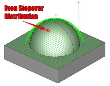
Figure 1. Mill three-axis equidistant toolpath operation.
With feature-based CAD/CAM, you can also add rough and finish toolpath operations in one feature. For example, setting up the mill three-axis feature for the glass bottle mold pictured is easy. Simply create a new mill three-axis feature. Then, add advanced rough and equidistant toolpath operations. Set up parameters in the feature and hit compute.
If you need your parting line to be sharp, you want to keep the tool away from the parting surface as the top of the stock has already been faced off. This can be accomplished inside the equidistant operation on the parameters page. You can add a top-of-job to limit the tool path in the Z direction and avoid the parting surface.

Chart 1. Depth options in equidistant feature wizard.
Here, we used a 1/8-inch-diameter ball end mill to finish the part. The machine origin work offset location is set to the top of the stock. Set the top-of-job down by the radius of the tool to eliminate any extra unnecessary tool path (see Chart 1). This will avoid the tool path from rolling over the top edge of the mold. See Figure 2 for the result of the computed tool path.
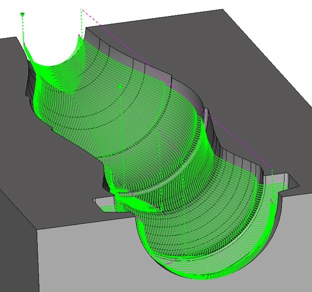
Figure 2. Glass bottle model using a computed equidistant toolpath operation.
Improve CNC Finishing Tool Path
There are many ways to improve the effectiveness of the finishing tool paths. As shown in Figure 2, you can use the equidistant tool path to get an even stepover distribution. However, other important concepts you can use to improve tool wear and cycle times are corner slowdown and rest finishing.
Corner slowdown is a new and important option to use within the equidistant tool path. With this option enabled (see Chart 2), the CAD/CAM software intelligently reduces the feed rate gradually as it approaches corners, thus enabling users to execute faster feed rates throughout the entire part. This means reduced cycle times, improved tool wear, less reliance on manual feed rate adjustment at the machine and confidence in an automated process.

Chart 2. Depth options
Rest finishing cleans up any nonmachined areas that remain after all other tool paths are complete. For example, you can add one advanced rough and two equidistant operations to a feature. In the second equidistant operation, enable rest finishing and use a smaller tool. The tool path computed will only show up in areas the larger tool missed.
Let’s go back to the glass bottle mold example. There are radii in the mold cavity surfaces that were smaller than 1/16 (0.0625) inch. This means that our 1/8-inch-diameter ball end mill tool will not be able to fit into those areas. This leaves excess material and requires additional tool path to clean up. You must return with a smaller tool and create a tool path in those areas to clean up the radii. Using the rest finishing option can accomplish that cleanup.
There is no need to use a smaller tool for the entire finish tool path. You can save extra time by using the rest finish option instead. You can also limit the wear on smaller tools because you only machine smaller portions of the mold.
Here are three options for setting up rest finishing:
- Tool from Previous Operation. The software uses the previous operation to calculate the rest finish.
- User-Defined Tool. You can manually define the previous tool information.
- Stock STL. You can import an STL of stock. The software then compares the STL model with the part and creates the rest finish tool path based on this data. This is useful if you have two separate jobs for the part. You can save the partially complete STL stock from the simulation and import it into your second job.
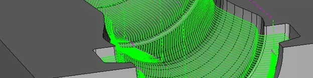
A previous equidistant tool path is inside the feature, so for the bottle mold example, we used a tool from previous operation (see Figure 3).
Apply the Right Five-Axis Machining Toolpath Strategy
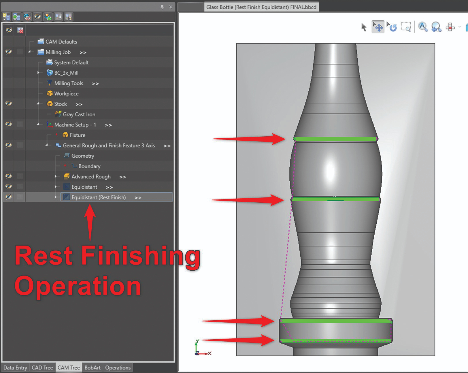
Figure 3. Illustrates the result of an equidistant rest finish operation.
Some CAD/CAM can be fully utilized for two- to five-axis machining. The tool paths for mill can range from 2½-axis to five-axis simultaneous motion and deburring, multiblade and port machining.
To access five-axis tool paths, create a mill multiaxis feature. You can choose from surface-based tool paths to machine-specific surfaces on the model. You can also select multiaxis machining for five-axis roughing and floor, wall and rest finishing.
The tool path in Figure 4 uses a multiaxis-machining, wall-finishing strategy so that you can use a barrel/circle segment cutting tool. This tool path uses all five axes, enabling the tool path to run along the walls and machine the part. You can also set up minimum and maximum contact points to restrict where the cutting tool contacts the part. Some of these tool paths also enable a three- to five-axis motion and a deburring tool path that rolls along the sharp edges of parts to remove any burrs or sharp corners. This tool path also identifies edges on selected surfaces and creates tool paths accordingly. You can select specific areas that you want to machine if you do not want to machine the entire part.
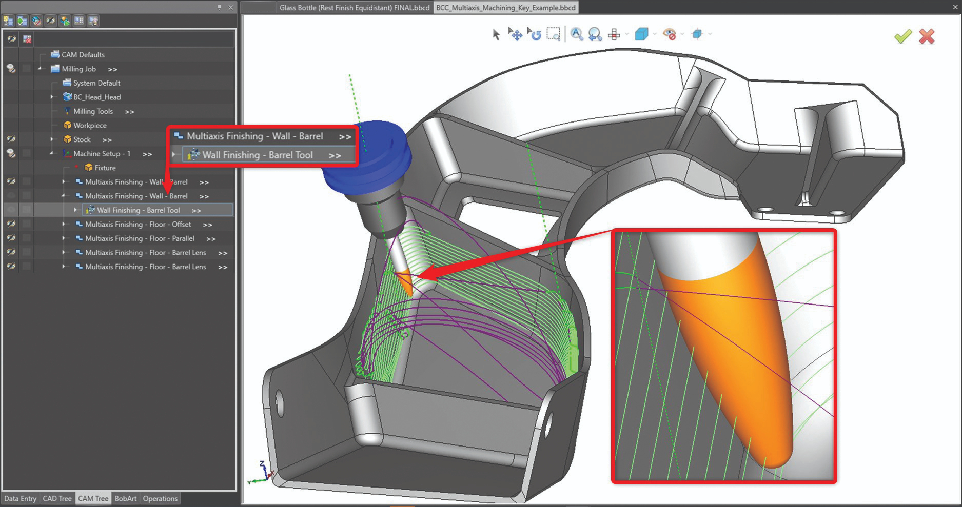
Figure 4. Illustrates a multiaxis-machining, wall-finishing strategy.
This article only scratches the surface of what five-axis tool paths can do — including fully customizing the output of the tool path whether you want to control the tool orientation for three, four or five axes.


Related Content

Mold Innovations Power Unique Auto Lighting Elements on Hummer EVs
Diamond machining, electroforming of micro-optical inserts and modified latch-lock system help injection molds produce unique forward lighting elements.
Read More
Tolerancing in Mold Design, Part 2: Using GD&T to Address Conventional Tolerancing Issues
Mold designers can achieve a single interpretation of workpiece functionality when following the American Society of Mechanical Engineers Geometric Dimensioning and Tolerancing standard.
Read More
MoldMaking Technology's Most-Viewed Content 2022: Products
MMT shares the five top-viewed technologies, equipment and services of 2022 in each Engineer, Build, Maintain and Manage tenet based on Google Analytics.
Read More
Mold Design Review: The Complete Checklist
Gerardo (Jerry) Miranda III, former global tooling manager for Oakley sunglasses, reshares his complete mold design checklist, an essential part of the product time and cost-to-market process.
Read MoreRead Next

How to Use Continuing Education to Remain Competitive in Moldmaking
Continued training helps moldmakers make tooling decisions and properly use the latest cutting tool to efficiently machine high-quality molds.
Read More
How to Use Strategic Planning Tools, Data to Manage the Human Side of Business
Q&A with Marion Wells, MMT EAB member and founder of Human Asset Management.
Read More
Are You a Moldmaker Considering 3D Printing? Consider the 3D Printing Workshop at NPE2024
Presentations will cover 3D printing for mold tooling, material innovation, product development, bridge production and full-scale, high-volume additive manufacturing.
Read More